Control Panels

Making more control panels, this one is on the hidden staging level. It routes the trains either up to main level via a grade or routes the train into the west staging yard. Panels are constructed on 1/8″ Masonite. I use PowerPoint to generate the graphics, printed on 3M permanent shipping labels. The kind made so they hide what’s behind. I then cover with a self adhesive laminate sheet.

20130228-082633.jpg

Posted in Construction, Electronics, Signaling / CMRI | Tagged , , , , , | Leave a comment

Sorry, couldn’t help it

Sorry, couldn’t help it he was just to cute.

20130228-081643.jpg

Posted in Dog Stuff | Leave a comment

Roadbed Heaven

From the “life is good” file…. Hey honey check and see if your work has any 1/2″ Homasote? If they do get my a 4×8 sheet, have them cut it unto 3 pieces – 32×48. And when I got home…20130222-083158.jpg

Posted in Construction | Tagged , , | Leave a comment

Building DCCODs

Got down to the basement to build some of Bruce Chubb’s DCCOD occupancy detectors. I have 21 to build, building these circuits yourself helps keep the costs down and it’s fun.

20130111-134343.jpg

20130111-134400.jpg

20130111-134412.jpg

Posted in Electronics | Tagged , , , | Leave a comment

Basement Train Whistle / Air Horn

Basement Train Whistle / Air Horn


I wanted a train whistle in my basement and here’s how I went about it.


A long time ago I purchased an aluminum Train Whistle. It had a good sound when you blew into it, but that has it’s limitations. So, I went about to fix that. I already had compressed air in the basement for painting so I just tee’d of it with another regulator and gauge. This line ran over to where I mounted the whistle. I then made an adapter for an Air Blow Gun to fit into the end of the whistle. I took a long eyebolt and attached to the blow gun’s lever and added a return spring for good measure. This worked well. I then ran a rope the length of the basement with a fancy handle at my favorite spot. The rope can be pulled anywhere along the line and actuate the whistle. I can adjust the pressure to suit. (about 80psi). Check out how it sounds….    Basement Train Whistle / Air Horn

Posted in Construction, Signaling / CMRI | Leave a comment

Layout Lighting (Don’t have a catchy title for this one)

Layout lighting is another area where there are many trains of thought (that was pretty catchy-though). Florescent tubes are one option… with this method there are choices for tube color, number of tubes, fixture spacing and a concern of UV rays fading your scenery. I tried this option… the fixtures were expensive, cumbersome to install, hard to fit in space allowed, did not flow around corners, hard to obtain the color I wanted and did not give off enough light (sort of explains why I’m against them).

Another option is incandescent lighting. Generally speaking this method generates to much heat.

Best Railroad Lighting Fixture

 I opted for a highbred combination that includes all of the best features and none of the drawbacks….My lighting uses low cost Medium Base incandescent fixtures to hold Compact Fluorescent bulbs. The bulbs run cool, they are cheap (now anyways), they come in all the colors and I can pick the wattage to achieve the level of brightness I desire.  The wiring is a simple bus type arraignment, just Tee in as many lamps as you need. I am using 60w bulbs spaced at 1 foot intervals. For the color I alternate between Bright White (3500k) and Daylight (5000K). This gives me a natural color I feel is right.

Lighting Valence

 All this is covered with valence made with dropped ceiling components and a cracked ice panel. This gives the ceiling a finished off look. All this came from Home Depot. Lighting is complicated to get right, I hope with some of these suggestions you can avoid all the trials I have been through.

Model Railroad Light FixtureModel Railroad Light Bulbs

Posted in Construction, Electronics | Leave a comment

When Animals… ATTACK

I had to store my Time Saver layout in the garage over the winter and this is what happened. Some animal got in and stayed a few weeks and he was eating the scenery. I think it was a squirrel….These photos are after I cleaned up the mess, but he/it even chewed up one of the vehicles. So…. BEWARE when Animals…  ATTACK.

Animal eating my scenery


 Animal eating my scenery 2


Animal eating my scenery 3Why would it want to eat my scenery?

Posted in Construction, Scenery | Leave a comment

Modular Club – Wiring Challenges

Just got a call on Saturday from the Big Guy “Leonard”, he called and was asking about some wood, well anyway he mentioned the Club’s next set-up at the Fox Run Retirement Village on June 2 & 3rd. He also mentioned that at the previous set-up they had problems with the A/C power hook-up, as they had to run a long extension cord to power the modules. That led to this Blog…..

Modular railroads feature many challenges from track alignment, portability, construction  and wiring issues. With the Ford Model Railroad Club having 2 scales and no set track plan these challenges are multiplied times 10. This entry will concentrate on Wiring.

 Wiring on a base, 4 foot module uses Cinch-Jones type electrical connectors with 2 pins each for the HO Scale and 4 pins each for O Scale. Corners are similar although each is wired in a Non-Standard pattern to allow for flexibility and they will always be positioned in the same location in relation to each other. Wiring is based on the NMRA modular standard, which was revised to include the 2 extra mainlines.Base Module Wiring Standard

Here is the general convention with the HO scale track indicated in red and being called front of the module. As shown  120V male is located to the right side. All Male connectors are located to the right side when viewed from the front as shown. Female connectors are located to the left side (not shown here). Wiring the modules in this way allows for each of the base modules to be positioned anywhere in the layout. Wiring Plan Ford Model Railroad Club

Overall plan is shown next (track connectors omitted for clarity). Sides can be adjusted to add any number of modules or none at all (corner mated to corner). Emphasized here is the AC power distribution around the layout, what ends up happening is that in the process of making the modules interchangeable you create 2 – AC circuits. These start at a common point A with each going half way around the layout and ending at B. An extension cord connects the 2 circuits to the wall (AC Source). 

Wiring Plan   Next I have included a power point document (this is fun)… the original of the diagram above. What is cool about this, is with Power Point you can group objects and move them around. Go ahead and play with it. Open the file and save it to your computer. With the document open, click on a side module, dots will appear showing you have selected an item. Next; using the left, right, up and down buttons, move the module where you would like it to be. Sometimes you will need to move the item one step beyond and then bring it back to get it to line up. Right click on a module, then copy/paste to create more modules for any side or click/delete key to remove any module. Then move the corners into place. Have fun and see all the possibilities. (0 x 8), (4 x 4), (1 x 4 shown)

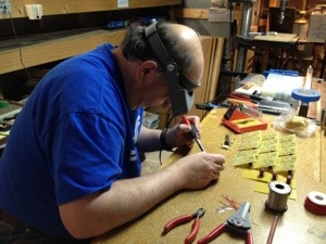
Wiring has been one of the more difficult aspects of club/modular railroading. People always tend to take shortcuts. Sitting on a cold concrete floor, staring upward as you try not to bang your head on the cross brace doesn’t help. These challenges can be over come.
1) Follow the plan / standard. Take your time to understand what the plans mean. Get help if you don’t understand something.
2) Use color coded wire. Even though the standard says Zip Cord is approved. Spend a little extra and color code your wiring.
Color code connectors. Clearly mark your connectors.
3) Make the jumpers long enough. Standard recommends 20″ jumpers on the right side for a reason. These allow you to make the connection with the adjacent module conveniently and not have to pull on the wiring
4) Use terminal strips. Not mandatory, but I like them and they allow you make changes easily.
5) Track Feeders. Every piece of track gets a feeder, longer pieces (like 3Footers) 2 feeders would be better.
6) Check each connector pin with an Ohm Meter.
7) Do all these at the bench where you can do it comfortably sitting in a chair. Not under the layout minutes before the show starts.

These may sound like simple rules, but it happens time and time again that people don’t follow them. Hope this doesn’t come across as to much of a downer… but as stated in the introduction, wiring for modular layouts get complicated in a hurry and the Ford Model Railroad Club’s dual scale layout is at a complexity level an order of magnitude higher. So get the wiring right, save yourself complications later and have some fun running trains. See the video….http://www.carmancraft.com/FMRCgallery1.htm

Note: NMRA Wiring Standards  http://www.nmra.org/standards/modules/mrp-1_3.html

Posted in Electronics | Leave a comment

The Great Puff Ball Debate….

I posted this over at Model Railroad Hobbyist Magazine     http://model-railroad-hobbyist.com/node/8034         But here is the gist….

Hi every one…I am struggling at making trees. Joe makes the pine tree scenery look so good, us plain old folks trying to model eastern railroads don’t have a chance. So here is the issue… how do we make realistic eastern type forests of trees? I have never been a real fan of the puff ball. Model Railroader used them on their Virginian project railroad and it doesn’t have the realism I am looking for (see – Joe has spoiled it for the rest of us). Attached is my attempt at modeling them, how about some suggestions and hints….

Image for Puff Ball Tree Discussion


I am using Woodland Scenics clump foliage and ground foams… backdrop still needs the misting of white and some distant hills painted on it. Thank for your suggestions.


This second picture gives a closer look at the foliage and I like the leafy texture.

The Joe, I am referring to is Joe Fugat from Model Railroad Hobbyist fame, he is a very good modeler and I have some of his how-to Videos. He is the best. But… he models Western U.S. pine tree scenery. Not Eastern United States and it is different.

Next picture is of Allen McClelland’s V&O railroad, a fabulous railroad but this is not the look I am trying to achieve.

So….Follow along a let me know what you think about puff ball trees.


Posted in Construction, Scenery | Tagged , , , , , , , , , , | Leave a comment

Hidden Staging – expanding beyond…..

Staging is an area of model railroading that has changed over the years. At first the concept did not exist, railroads could only handle as many cars as you could see or hold on the visible portion of the layout. That evolved into staging yards, holding cars and trains waiting to move into view. These were either hidden above, below or behind. Staging even went another step further as to staging your cars on a visible portion of the railroad.

Staging Yard

For my railroad I chose to model 2 staging yards and I placed them on a lower level. There is an East and West yard, they each have 6 tracks that are at least 10′ Long (One of my design criteria). Shown in the first picture is the general layout of the East Yard. The levels are 12″ apart and there is just enough room for access. I chose this separation as to limit the grade to 2.5% or less.

The idea behind this type of staging is that you expand the layout beyond your physical boundaries. A train entering the visible portion from the East Yard could be coming from anywhere you choose. There is hardly any limit, some even exchange cars from other model railroads.

To make this expansion work you will have to go the extra mile in regard to trackwork… the track and turnouts must be installed with care and thoroughly tested. All turnouts are powered with Tortoise switch machines controlled by CMRI outputs. There are Atlas re-railers at the beginning and end of every track, along with foam bumpers to ease the stop.

East Staging - End

Turnout, track body and track ends all are on separate detection zones. An LED will alert you as you enter the track, clear the switch (actually on the staging track) and when to stop (final 6″ to a foot).

Second photo shows the re-railers and bumpers. Detection gaps can be seen cut into one side of the re-railers.

Third photo shows the DCCOD Occupancy Detectors, wiring and some of my wiring conventions as to marking of zones and labeling wires. NOTE: keep your wiring neat, labeled and take notes.

Detection Zone

With these 2 staging yards I have expanded my layout beyond the physical boundaries of my basement, I can run more trains without repeating a train and with careful track work and electronics this will be accomplished with little to no hassle.


Posted in Construction, Electronics, Signaling / CMRI | Tagged , , , , , , , , , | Leave a comment