Just got a call on Saturday from the Big Guy “Leonard”, he called and was asking about some wood, well anyway he mentioned the Club’s next set-up at the Fox Run Retirement Village on June 2 & 3rd. He also mentioned that at the previous set-up they had problems with the A/C power hook-up, as they had to run a long extension cord to power the modules. That led to this Blog…..
Modular railroads feature many challenges from track alignment, portability, construction and wiring issues. With the Ford Model Railroad Club having 2 scales and no set track plan these challenges are multiplied times 10. This entry will concentrate on Wiring.
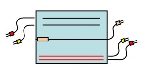
Wiring on a base, 4 foot module uses Cinch-Jones type electrical connectors with 2 pins each for the HO Scale and 4 pins each for O Scale. Corners are similar although each is wired in a Non-Standard pattern to allow for flexibility and they will always be positioned in the same location in relation to each other. Wiring is based on the NMRA modular standard, which was revised to include the 2 extra mainlines.
Here is the general convention with the HO scale track indicated in red and being called front of the module. As shown 120V male is located to the right side. All Male connectors are located to the right side when viewed from the front as shown. Female connectors are located to the left side (not shown here). Wiring the modules in this way allows for each of the base modules to be positioned anywhere in the layout. 
Overall plan is shown next (track connectors omitted for clarity). Sides can be adjusted to add any number of modules or none at all (corner mated to corner). Emphasized here is the AC power distribution around the layout, what ends up happening is that in the process of making the modules interchangeable you create 2 – AC circuits. These start at a common point A with each going half way around the layout and ending at B. An extension cord connects the 2 circuits to the wall (AC Source).
Wiring Plan Next I have included a power point document (this is fun)… the original of the diagram above. What is cool about this, is with Power Point you can group objects and move them around. Go ahead and play with it. Open the file and save it to your computer. With the document open, click on a side module, dots will appear showing you have selected an item. Next; using the left, right, up and down buttons, move the module where you would like it to be. Sometimes you will need to move the item one step beyond and then bring it back to get it to line up. Right click on a module, then copy/paste to create more modules for any side or click/delete key to remove any module. Then move the corners into place. Have fun and see all the possibilities. (0 x 8), (4 x 4), (1 x 4 shown)
Wiring has been one of the more difficult aspects of club/modular railroading. People always tend to take shortcuts. Sitting on a cold concrete floor, staring upward as you try not to bang your head on the cross brace doesn’t help. These challenges can be over come.
1) Follow the plan / standard. Take your time to understand what the plans mean. Get help if you don’t understand something.
2) Use color coded wire. Even though the standard says Zip Cord is approved. Spend a little extra and color code your wiring.
Color code connectors. Clearly mark your connectors.
3) Make the jumpers long enough. Standard recommends 20″ jumpers on the right side for a reason. These allow you to make the connection with the adjacent module conveniently and not have to pull on the wiring
4) Use terminal strips. Not mandatory, but I like them and they allow you make changes easily.
5) Track Feeders. Every piece of track gets a feeder, longer pieces (like 3Footers) 2 feeders would be better.
6) Check each connector pin with an Ohm Meter.
7) Do all these at the bench where you can do it comfortably sitting in a chair. Not under the layout minutes before the show starts.
These may sound like simple rules, but it happens time and time again that people don’t follow them. Hope this doesn’t come across as to much of a downer… but as stated in the introduction, wiring for modular layouts get complicated in a hurry and the Ford Model Railroad Club’s dual scale layout is at a complexity level an order of magnitude higher. So get the wiring right, save yourself complications later and have some fun running trains. See the video….http://www.carmancraft.com/FMRCgallery1.htm
Note: NMRA Wiring Standards http://www.nmra.org/standards/modules/mrp-1_3.html
